Overview
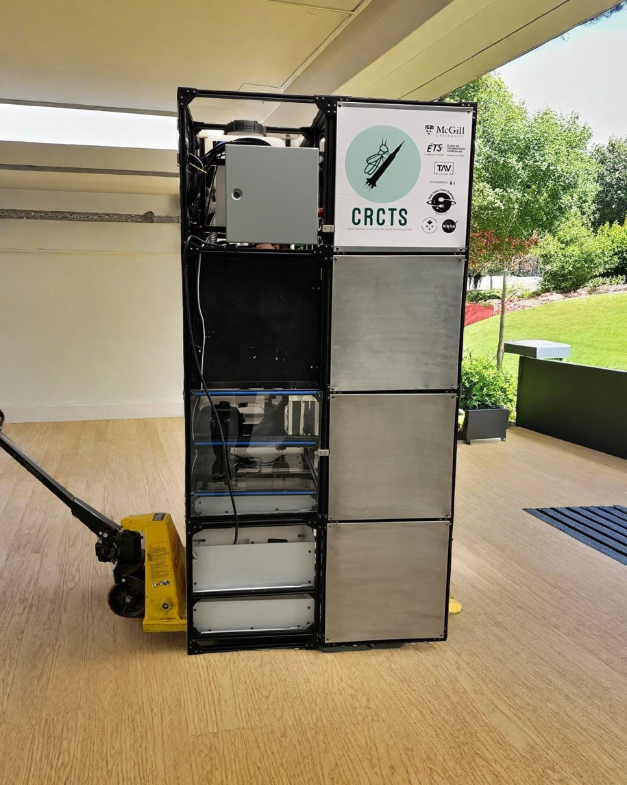
The “Deep Space Food Challenge” organized by NASA and the Canadian Space Agency aimed to develop innovative food systems for use in outer space. Our team, composed of diverse engineering backgrounds from various Canadian universities, successfully presented a full-scale food production system using crickets as a food source. This competition began in 2021 and recently concluded, with significant accomplishments in both hardware and software development.
As the embedded systems lead, my key contributions included:
-
- Designing three software frameworks for intercommunication via the MQTT protocol, handling nearly 50 instructions.
-
- Standardizing the system architecture by assigning IDs to 48 trays and 12 units to ensure seamless communication and avoid conflicts.
-
- Reducing execution time on embedded devices by parallelizing critical components using FreeRTOS, multi-core handling on ESP32, and threading on Raspberry Pi.
-
- Creating a central server on Raspberry Pi to manage incoming and outgoing MQTT messages and update the main JSON file, which is reflected on the website dashboard.
-
- Enabling full control of critical components (humidifier, heating, LEDs) and live footage viewing via the website.
-
- Adding security by setting up a VPN server on Raspberry Pi, restricting website dashboard access to VPN users only.
-
- Streamlining the production process to efficiently produce and install 48 electronic boards in the system.
The team, named CRCTS (Cricket Rearing, Collection, and Transformation System), achieved remarkable success, and I am proud to have been a part of this journey.
Hardware Design
The PCB design was made with EasyEDA Pro software. This allowed us to have other hardware engineers to collaborate with each other via the web application. The design was broken down into 3 separate designs namely:
- Primary Board (contains the main controller and power control board and others)
- Tray Connector
- Sensor Connector
Main Features
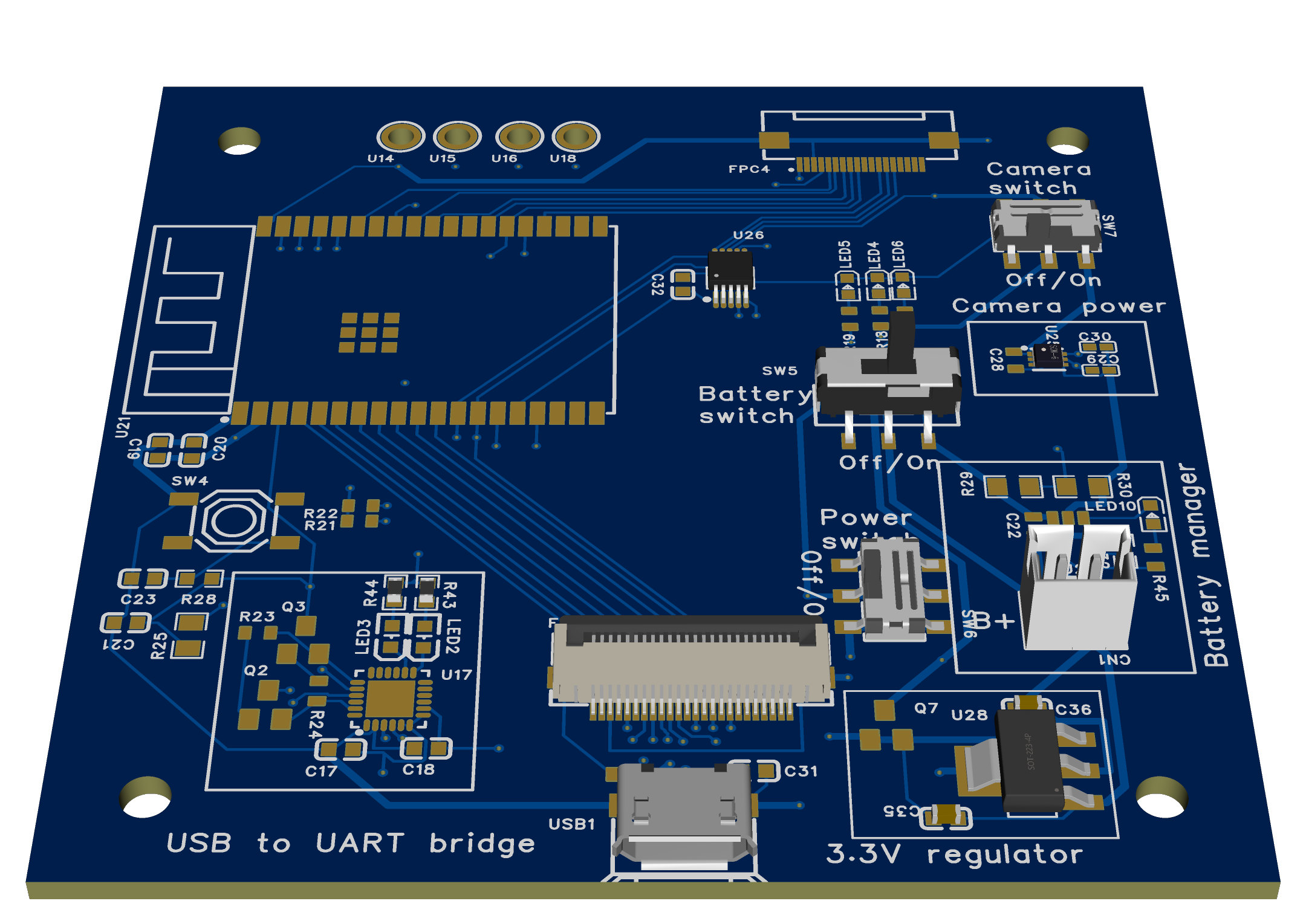
- ESP32 WROVER N8R8
- Camera
- USB to UART bridge
- Battery
- Battery manager
- I2C bus
- Display
- 3.3V LDO
- Camera LDO
- I2C ADC
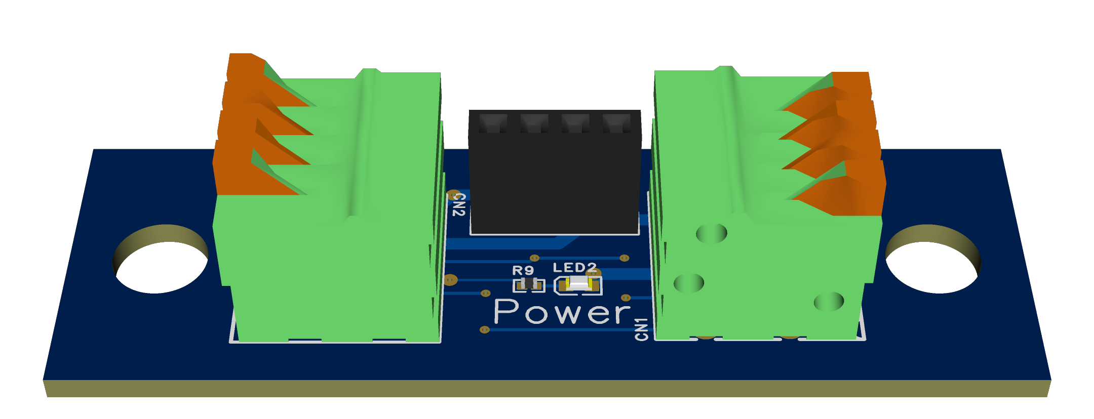
The PCB design are shown below:
Primary Board
Tray Connector
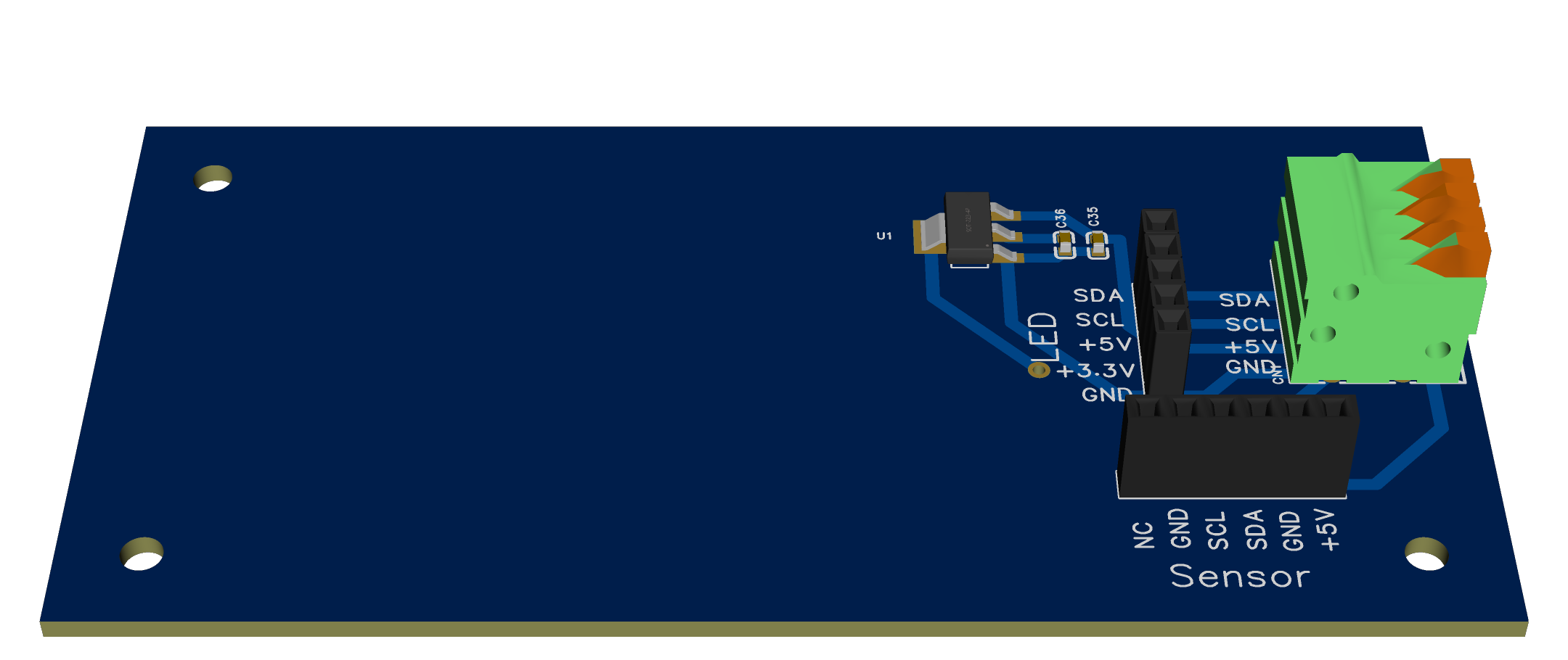
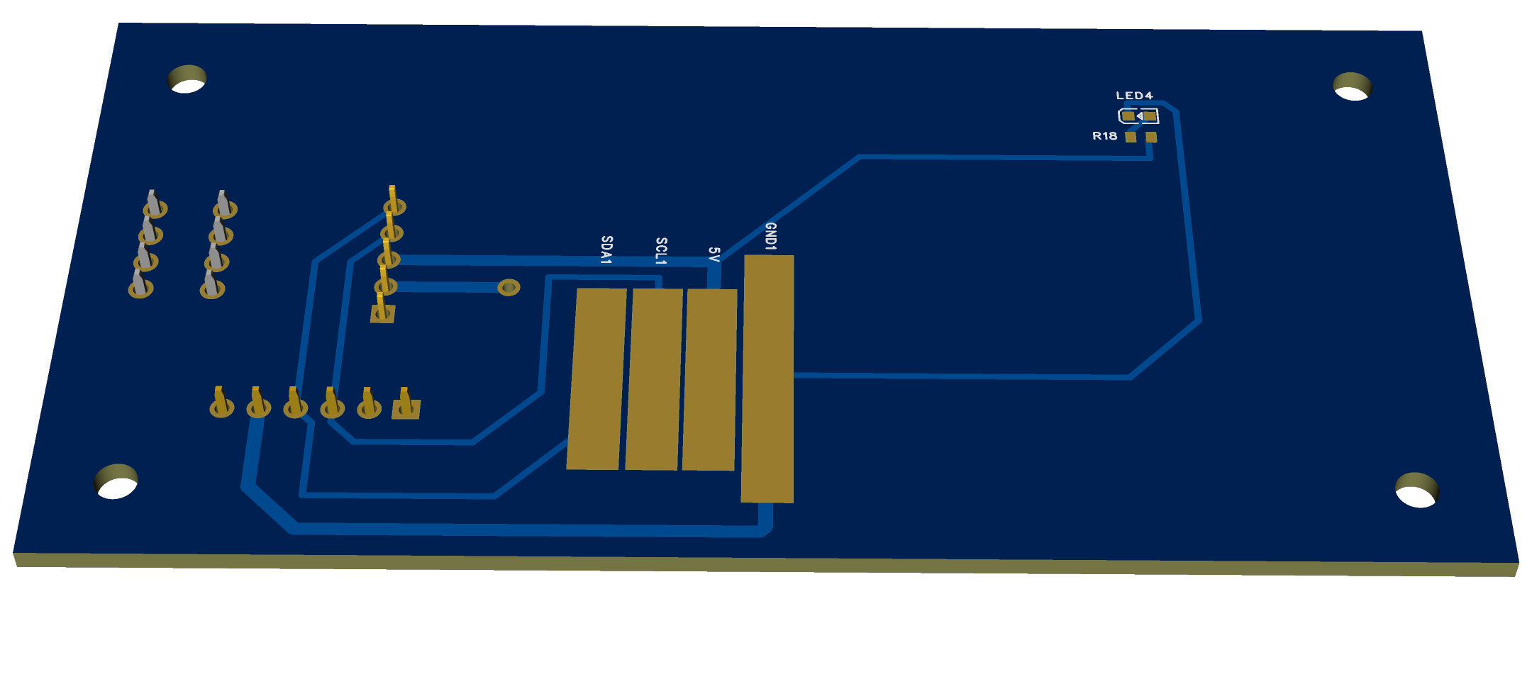
Sensor Connector
Software Design Architecture
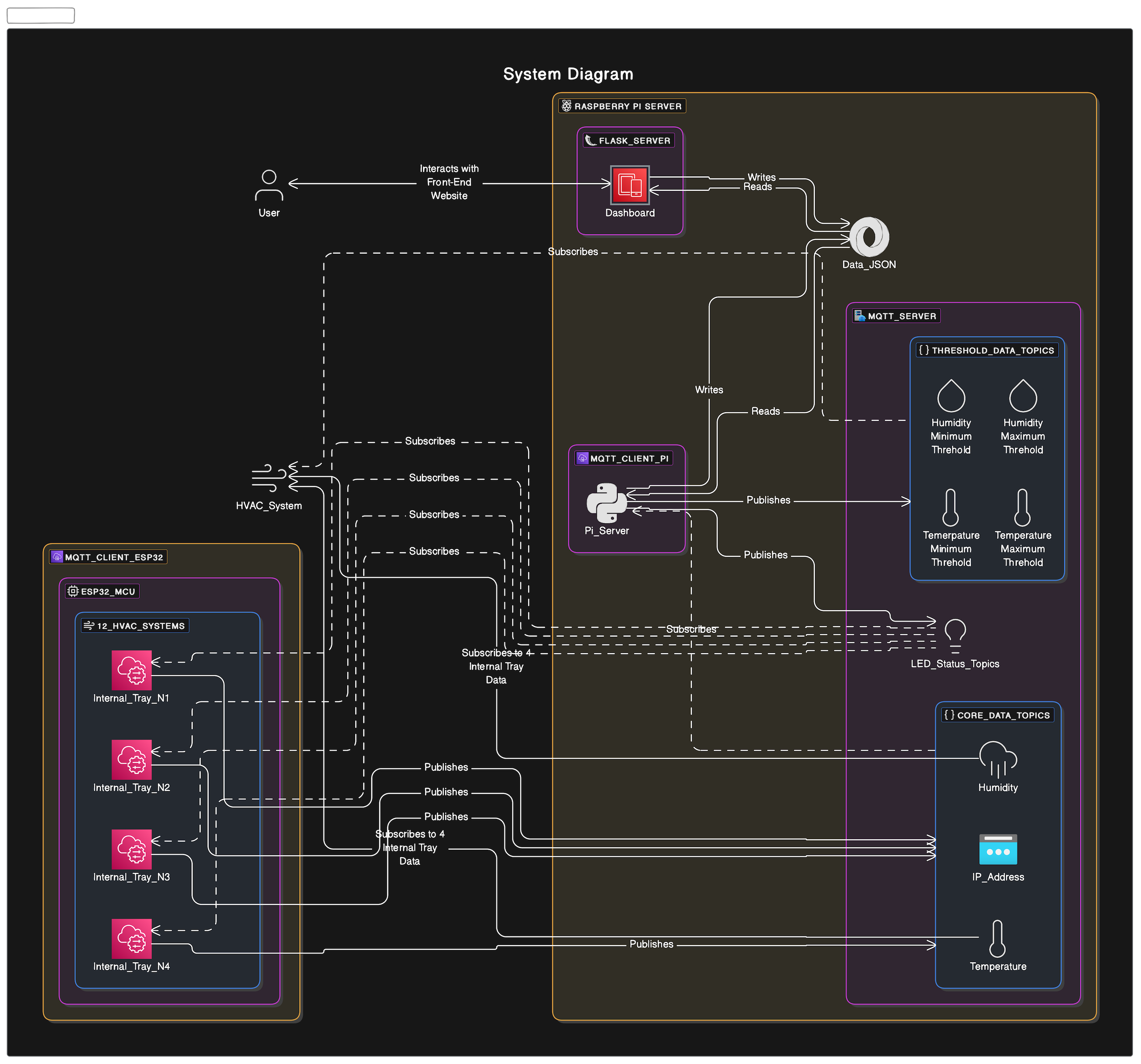
Internal Tray
- Record sensor readings
- Periodically turn on/off LED light for day/night lifecycle for crickets
- Send esp32’s ip address and sensor readings to Raspberry Pi Server
- Receive thresholds and manual overrides of LED lightings from Raspberry Pi Server
- Send thresholds and sensor values to HVAC Unit
- Display sensor values, camera status and thresholds on the LCD display
HVAC System
- Receive threshold and sensor values from Internal Tray
- Average the the sensor values from four trays for one unit
- Activate humidity, heater and cooler based on the thresholds
Raspberry Pi Server
- Receive Internal Tray IP Addresses and sensor readings
- Send IP Addresses and sensor readings to Website
- Receive the thresholds and manual overrides from the Website
- Send threshold and manual overrides to Internal Tray
- Access camera footage based on user’s input and then send the footage to Website
Website
- Receive IP Addresses and sensor readings from Raspberry Pi Server
- Display the appropriate tray’s information (similar to Phase 2)
- Access video footage of specific tray on the website based on user input
- User able to change the threshold values on-demand
- Send thresholds and manual overrides for each trays to Raspberry Pi Server


